English
7QX40 - Square trusses 40 cm

View all


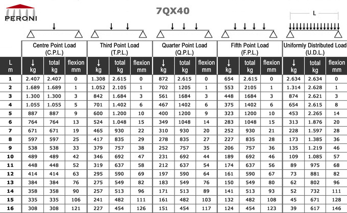
↓ - Center point load
↓ ↓ - Point load at 1/3
↓ ↓ ↓ - Point load at 1/4
↓ ↓ ↓ ↓ - Point load at 1/5
↓↓↓↓↓↓↓↓↓↓↓↓ - Uniformly distributed load
The load table was prepared in accordance with UNI ENV 1999-1-1 (Eurocode9).
When calculating the allowable loads shown in the table, it is assumed that the trusses are simply supported at the end connection and that static loads will be applied to the node points.
The application of the load shall be on the centre line of the truss.
The values shown in the table are the allowable statics loads that can be applied to the truss.
This is the live load or the payload.
The self weight of the truss was taken into account when calculating the values in the table.
It should be noted that these are idealised loading conditions and that the User shall re-analyze the truss for the loading conditions which prevail for the application being considered.
Cords
aluminium extruded tube Ø 50 x 2 mm - EN AW 6082 T6
Diagonals
aluminium extruded tube Ø 20 x 2 mm - EN AW 6082 T6
Ends
aluminium casting plate - EN AC 42200 T6
7QX40
Standard lengths of linear trusses
article
length ..... weight
. cm ............ kg
. cm ............ kg
7QX40 T 010
..10 ............ 4,6
7QX40 T 025
..25 ............ 5,5
7QX40 T 050
..50 ............ 6,5
7QX40 T 100
100 ............ 9,8
7QX40 T 150
150 .......... 13,5
7QX40 T 200
200 .......... 16,2
7QX40 T 250
250 .......... 19,8
7QX40 T 300
300 .......... 21,0
7QX40 T 350
350 .......... 26,6
7QX40 T 400
400 .......... 29,8